Hexapod, part 1 of 4
Design & build
From the CAD model of a single leg to a robot with twenty servos, a sensor turret and an onboard computer: the mechanical design, the sensors, the power system and the small circuit board that ties the servos together.
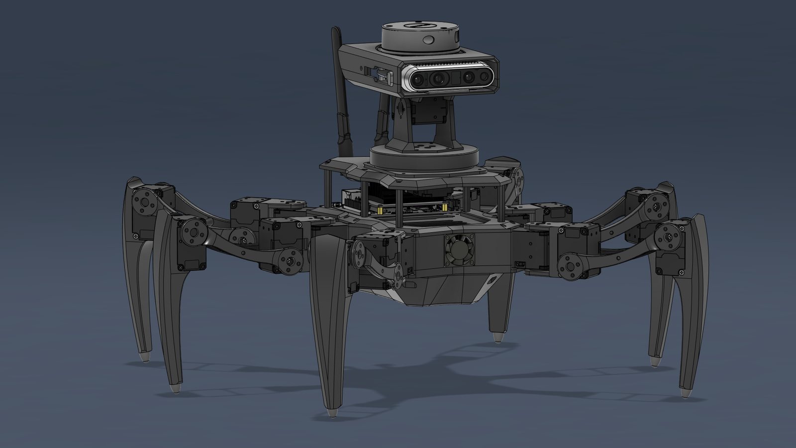
Starting point
The hexapod started as a hobby and learning project. I wanted to get hands-on with sensors I hadn't used before, depth cameras and lidars, and to learn ROS 2 and machine learning on a robot of my own. I started in April 2023 by modelling a leg.
I took a lot of inspiration from other builders' hexapods: François Ubald Brien's Mildred, Matt Bunting's Dmitri and DerelictRobot's Orwell.
Mechanical design
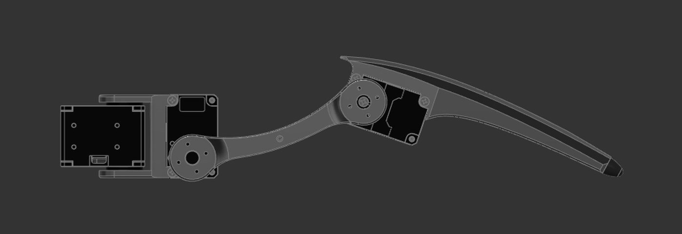
Each leg has three Dynamixel XL430 servos: the coxa servo swings it forward and back, and the femur and tibia servos lift and extend it. The printed links bolt directly to the servo horns and cases, so the servos themselves are part of the structure. The tibia is a long, curved blade ending in a small foot tip.
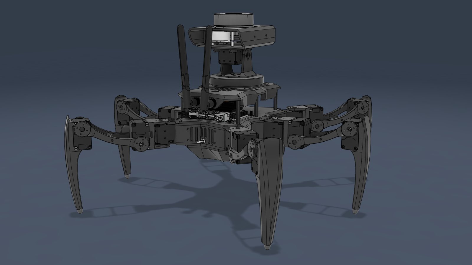
From the start I wanted a turret with a good camera on top. A hexapod suits that well: with three feet always on the ground, the body stays level and steady while it walks. The head pans and tilts on two more XL430s. The body is built in two levels: the leg servos bolt around the lower level, and the computer sits on the upper one, under the head.
Sensors
- Intel RealSense D435i. A stereo depth camera with a colour sensor, and an IMU built in. That IMU is the one the localisation filter uses (part 3), so no separate IMU board was needed. It also offers a lot for its price.
- Slamtec RPLIDAR A1M8. A 360° 2D lidar on top of the head. It's one of the most common lidars in hobby robotics, and well supported in ROS 2.
Both sit on the pan-tilt head, so the camera can look around without the robot turning.
Power & wiring
The servos want 11.1 V, while the original computer, a Jetson Nano, as well as the camera and the lidar, all run on 5 V. So everything starts from a 3S LiPo battery (11.1 V, 5200 mAh) and splits in two. The servos take the battery voltage directly, through a power hub. A buck converter steps the same supply down to 5 V, up to 4 A, for the Jetson. The Jetson then powers and talks to everything else over USB.
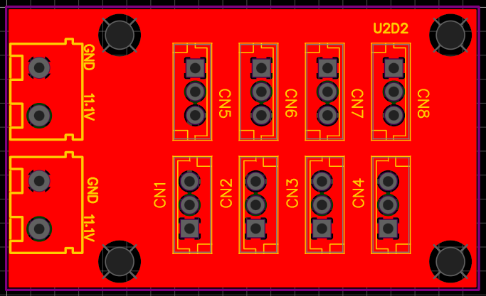
The servos chain together. Each leg is one cable from the hub to its coxa servo, then on to the femur and tibia servos. The head's two servos share the eighth port, the "neck". A U2D2 adapter from the Jetson provides the command line for the whole bus. At 1 Mbit/s, all twenty servos share it.
The power hub
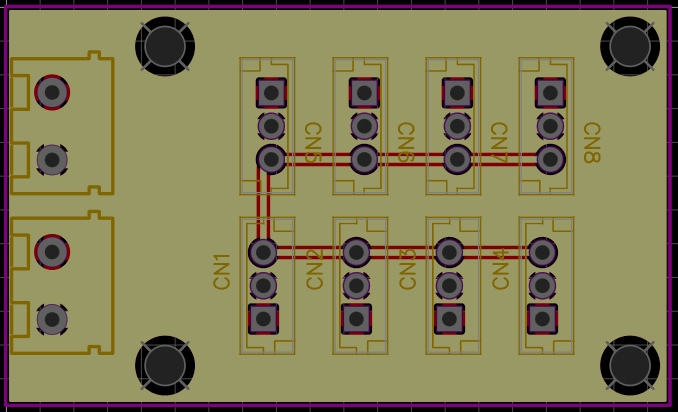
Twenty servos on one bus need a clean way to distribute both 11.1 V and the data line, so I designed a small two-layer board for it in EasyEDA. It has eight B3B-EH-A 3-pin connectors, the same JST EH type the Dynamixel X-series uses, so the servo cables plug straight in. Two power connectors bring in the battery and pass the supply on to the buck converter.
Computer & software platform
The first version ran on an NVIDIA Jetson Nano B01. Its JetPack 4.5 is based on Ubuntu 18.04, while ROS 2 Foxy targets Ubuntu 20.04, so ROS had to run inside a custom Docker container.
The robot now runs on a Jetson Orin Nano. Its JetPack is based on Ubuntu 22.04, so ROS 2 Humble runs natively, with no container in between, and there is far more GPU compute for perception and learned policies. For manual driving, an Xbox-style gamepad sends velocity commands, and its D-pad aims the head.
From there, the next step was making it walk: part 2 covers the kinematics and the gait controller.